
The design of the turbine wheel for a turbocharger must follow the establishment of a design point for the compressor. The compressor design point consists of the selection of the air mass flow and pressure ratio needed to match specific turbocharged engine air requirements. The mass flow of exhaust gas that the turbine wheel must be designed to operate on is the compressor mass flow plus the small additional quantity of mass added by the products of combustion of the fuel burned in the engine cylinder. Thus, the design mass flow for the turbine wheel is usually estimated at about 1.03 times the compressor mass flow.
Comp Turbo Bulletin No. 2 deals with exhaust manifold design and illustrates the pulsating exhaust gas flow that the turbine wheel is subjected to when the turbine with a divided turbine casing is mounted on a divided engine exhaust manifold. The turbine wheel must develop the horsepower needed to drive the compressor wheel at its design flow and pressure ratio and is designed on a steady flow basis with some appropriate allowances in the design for operation on pulsating exhaust gas flow.
The turbine power to be developed must include the bearing system losses and an estimate of friction and windage losses. Thus,
HPT = HPC + HPB + HPFW Where:
-
HPT = Turbine Power to be developed
-
HPC = Power required to drive compressor
-
HPB = Bearing system loss
-
HPFW = Friction and windage loss
The turbine inlet velocity triangle can be established once the turbine wheel tip speed has been calculated. A typical turbine inlet velocity triangle is illustrated below:

The inlet triangle shown above represents steady flow conditions. In reality, the pulsating exhaust gas flow will cause the value of C1 to vary with time. The inlet velocity triangles shown below illustrate the minimum and maximum values of the entering gas velocity.

The bulk of the exhaust gas flow occurs at the peak of the pulse. To minimize entrance losses, the design of the wheel should position the maximum values of the relative entering gas velocity to be as close to radial as possible.
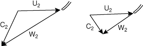
The turbine exit conditions have and important effect on the turbine efficiency. A typical exit velocity triangle at the geometric mean diameter is shown below:

The angle a, at the design point flow, determines the wheel blade angle at the exit. The value of C2 represents unrecoverable energy that is lost in the atmosphere when the gas leaves the wheel and this establishes the value of the leaving loss.
The value of C2 will vary with time because of the pulsating flow of the exhaust gas. The exit velocity triangles shown below illustrate the increased magnitude of the leaving loss at the peak of the pulse and the decreased magnitude in the valley between pulses.
Some Comp Turbo full bladed turbine wheels have exit blade diameters that are equal to the inlet diameter and, due to this design feature, the gas leaving velocity C2 is minimized, leading to the lowest possible leaving loss and this maximizes the turbine efficiency.
Our Bulletin No. 8 on the subject of turbocharger turbine efficiency shows the comparison of efficiencies of a contoured turbine and a full-bladed wheel operating on steady flow. The advantage of the full-bladed wheel with minimized leaving loss is characterized by the high efficiencies at very high mass flows. Graph No. 4 in Bulletin No. 8 shows actual test data of a pulsating flow turbine where efficiencies were found to be higher when the pulsations are maximum.